


 |
VDR 07D471K Voltage Dependent Resistor , 470V Surge Voltage Suppressor
Product Details:
| Place of Origin: | Guangdong,China |
| Brand Name: | JYVDR |
| Certification: | CQC,UL,TUV,ROHS,SVHC |
| Model Number: | JYVDR7D471K |
Payment & Shipping Terms:
| Minimum Order Quantity: | 10000PCS |
|---|---|
| Price: | 0.05-0.07 USD/PC |
| Packaging Details: | Tape in reel, 2000/reel,1.7kg/reel;10000pcs per outer carton,9.1kg per outer carton,40*39*19cm |
| Delivery Time: | 3-5 Workdays |
| Payment Terms: | T/T IN ADVANCE |
| Supply Ability: | 10,000,000 PIECES PER MONTH |
|
Detail Information |
|||
| Name: | Voltage Dependent Resistor | Color: | White |
|---|---|---|---|
| CQC #: | CQC18001202948 | UL #: | E481249-20180122 |
| TUV #: | B 094255 0002 Rev.00 | Varistor Voltage: | 470V±10% |
| VAC: | 300V | Max Energy: | 1000A (2000V) |
| Operating Temperature: | -40~125C | MOQ: | 3000PCS PER REEL |
| High Light: | 470V Voltage Dependent Resistor,07D471K Voltage Dependent Resistor,VDR Surge Voltage Suppressor |
||
Product Description
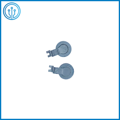
Voltage Dependent Resistor VDR 07D471K As Surge Voltage Suppressor or Surge Absorber
Description Of The Voltage Dependent Resistor VDR 07D471K
Varistors can be used as suppressors to protect devices and circuits from transient abnormal voltages including an ESD (electrostatic discharge) and a lightning surge.
For protection from a relatively large surge current (100A to 25kA), leaded disk varistors and SMD disk varistors are suitable. For protection from a larger surge current (approximately 25kA or more), block varistors, and strap varistors are suitable.
For industrial devices and energy apparatuses, disk varistors of which maximum allowable circuit voltage (rated voltage) and maximum peak current are large are used.
●Leaded disk varistors
●ThermoFuse varistors
●SMD disk varistors
●Strap varistors
●Block varistors
![]()
Features Of The Voltage Dependent Resistor VDR 07D471K
* Wide operating temperature -40~+125C
* Available in tape and reel packaging for automatic pick-and-place
* Certificated by CQC UL TUV
* Surface mount devices
* Fully automatic production line
Applciation Of The Voltage Dependent Resistor VDR 07D471K
Over-voltage and transient voltage protection:
• Data lines and I/O port protection
• Protection against ESD transients
• On-board protection of IC’s and transistors
• Modem protection
• LCD protection
● Sample application: Surge protection for the input part of a switching power supply
● Sample application: Surge protection for a LED lighting system
● Sample application: Surge protection for inductive loads such as motors
● Sample application: Surge protection for a motor with an electromagnetic brake and protection for the contact of its switch
● Sample application: Surge protection for an SSR (solid-state relay) and protection for its output terminal
● Sample application: Surge protection against load dump and field decay
● Sample application: Surge protection for joint boxes and power conditioners of solar power generation systems
● Sample application: Surge protection for important devices using a lightning transformer
● Sample application: Protection against a high-energy surge in industrial devices
Agency Approvals Of The Voltage Dependent Resistor VDR 07D471K
| Certification | CHINA | CQC | GB/T10193-1997 |
07D:CQC18001202948 |
| USA/Canada | UL | UL1449 | E481249-20180122 | |
| Germany (EU) | TUV | IEC61051 | B 094255 0002 Rev.00 | |
| ROHS | SGS/SVHC | SGS is updated annually SVHC is effective for a long time |
07DSGS:CANEC2121716204 SVHC:CANEC2200885702 |
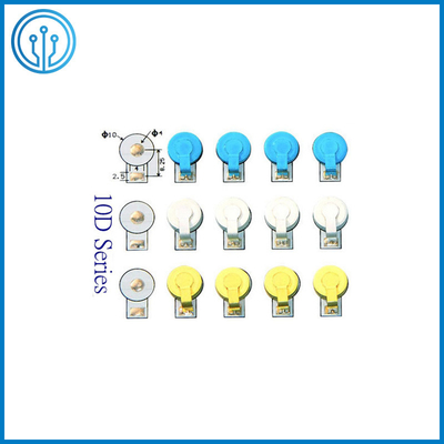
Dimensions, Appearance Identification Of The Voltage Dependent Resistor VDR 07D471K(mm)
![]()
![]()
Highly Recommended:
1. In the drawing board, it is recommended that the A solder joint be used as the L line, the B solder joint
as the N line, and the copper skin connected to the B solder joint is routed around the pressure-sensitive
chip circle (the entire diameter D should be regarded as belonging to the A solder joint.
2. For the sake of safety arcing, the circular edge of the chip should be at least 2.5mm away from any other
conductive device, as shown in the figure above (in order to prevent mutual displacement with other devices
during patching, if the space allows, please reserve the larger the interval is. Okay.)
3. The use of varistors in DC circuits has unfavorable factors. It is not recommended to use varistors in
rectified DC circuits. Please consider carefully or contact our company at 18128566098 (sales1@ampfort.net),
thank you!
| Model JYVDR~ |
Pad A | Pad B | Pad center distance C | Diameter D | Height H±1.0 | Thickness T | Coating material and remarks (insulating paint) | |
| Φa | b1 | b2 | ||||||
| 05D271 | 2.7 | 3.5 | 2.5 | 5.75 | 5.0 | 9.1 | 2.0 |
Blue 271:270VDC±10%; White 471:470VDC±10%; Yellow 511:510VDC±10%; Red 561:560VDC±10% 15 inch reel tape(MPQ): |
| 05D471 05D511 | 3.0 | |||||||
| 07D271 | 3.3 | 3.8 | 2.5 | 6.75 | 7.0 | 11.1 | 2.0 | |
| 07D471 07D511 07D561 | 3.0 | |||||||
| 10D271 | 4.0 | 4.0 | 2.5 | 8.25 | 10.0 | 14.2 | 2.0 | |
| 10D471 10D511 10D561 | 3.0 | |||||||
| 05D 07D 10D All series use 15-inch reel and 24-inch feeder placement machine | ||||||||
Electrical Performance Of The Voltage Dependent Resistor VDR 07D471K
| Model JYVDR~ |
Varistor Voltage | Max Allowable Voltage | Max Clamp Voltage(8/20us) | Max Energy | Max Static Power | Capacitance | Leakage Current | Approved Temperature | ||
| VDC | VAC | VDC | VDC | IP | Combined wave(A) | W | pF | (℃) | ||
| 05D271 | 270±10% | 170 | 220 | 480 | 8A | 500A(1000V) | 0.1 | 100 | ≤20uA | -40~125 |
| 05D471 | 470±10% | 300 | 380 | 810 | 10A | 65 | ||||
| 05D511 | 510±10% | 325 | 415 | 870 | 60 | |||||
| 07D271 | 270±10% | 170 | 220 | 450 | 15A | 1.0KA(2000V) | 0.25 | 170 | ||
| 07D471 | 470±10% | 300 | 380 | 770 | 20A | 115 | ||||
| 07D511 | 510±10% | 325 | 415 | 840 | 110 | |||||
| 07D561 | 560±10% | 350 | 450 | 925 | 100 | |||||
| 10D271 | 270±10% | 170 | 220 | 450 | 35A | 2.0KA(4000V) | 0.4 | 380 | ||
| 10D471 | 470±10% | 300 | 380 | 760 | 40A | 250 | ||||
| 10D511 | 510±10% | 325 | 415 | 835 | 230 | |||||
| 10D561 | 560±10% | 350 | 450 | 920 | 210 | |||||
For different voltage application environments, we recommend the following pressure sensitive
combinations to provide overvoltage, surge and lightning stroke protection for ACLED.
| Working Voltage Environment |
Forestage Varistor Parameter | Back-end Varistor Parameter | Remarks |
| 110VAC±20% | 270VDC±10% | / | In view of the insufficient voltage withstand capability of the IC, the two-stage varistor can be upgraded to 4KV lightning protection. The user can choose the varistor size according to the requirements of the anti-surge level. |
| 220-230VAC±20% | 510VDC±10% | 470VDC±10% | |
| 240VAC±20% | 560VDC±10% | 510VDC±10% | The combination is recommended for users in Indian and Brazil. |
Since pressure sensitive resistor is easy to degrade under the environment with strong voltage fluctuation,
it is required to select the combination with high pressure sensitive voltage value as much as possible
under the premise that withstand voltage of IC (MOS tube) +lamp bead on lamp board is pretty high
and that voltage has a large fluctuation area; besides, it is necessary to select pressure sensitive
resistor with large circulation and volume as far as possible, without exceeding cost limit.
Curve diagram of wave soldering Of The Voltage Dependent Resistor VDR 07D471K
![]()
The picture above shows the approximate trend of the reflow oven temperature curve on the market. Our
SMD pressure sensor uses the silver electrode of the ceramic body as one of the welding electrodes.
Please pay attention to setting the oven temperature and time (if the highest temperature is 260°C,
please Note that the time is 3-8S, if it exceeds 30S, the protection effect of the varistor will be affected).
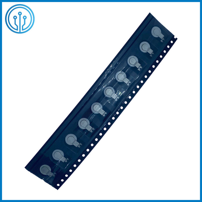
Package Of The Voltage Dependent Resistor VDR 07D471K
![]()
Precautions
1. The cumulative error of any 10 consecutive ratchet holes does not exceed ±0.2mm;
2. The non-parallel distance of 250mm in the length direction of the carrier tape shall not exceed 1mm;
3. The uninjected R angle is 0.2-0.3, and the uninjected demoulding slope is 5°;
4. Comply with EIA-481-D specification and ROHS requirements;
5. Thickness: 0.30±0.05mm;
6. The whole series of 05D 07D 10D adopts 15-inch reel and 24-inch feeder placement machine.
![]()
| Model JYVDR~ |
MPQ (QTY/REEL) (PIECES) | WEIGHT/REEL(KG) | QTY PER REEL(PIECES) | WEIGHT PER CARTON(KG) |
| 05D271 | 4000 | 1.5 | 20000 | 8 |
| 05D471 | 3000 | 1.5 | 15000 | 8.4 |
| 05D511 | 3000 | 1.5 | 15000 | 8.4 |
| 07D271 | 3000 | 1.8 | 15000 | 9.5 |
| 07D471 | 2000 | 1.7 | 10000 | 9.1 |
| 07D511 | 2000 | 1.7 | 10000 | 9.1 |
| 07D561 | 2000 | 1.7 | 10000 | 9.1 |
| 10D271 | 2000 | 2 | 10000 | 11 |
| 10D471 | 1500 | 2.2 | 7500 | 12 |
| 10D511 | 1500 | 2.2 | 7500 | 12 |
| 10D561 | 1500 | 2.2 | 7500 | 12 |
![]()