


|
Ceramic PTC Thermistor YS4020 Cross Resettable 1000V 1100 Ohm 20% Tol For Current Limiting
Product Details:
| Place of Origin: | Dongguan,Guangdong,China |
| Brand Name: | AMPFORT |
| Certification: | ROHS |
| Model Number: | MZ21-08D112M-102 |
Payment & Shipping Terms:
| Minimum Order Quantity: | 10000PCS |
|---|---|
| Price: | 0.3 USD/PC |
| Packaging Details: | Bulk |
| Delivery Time: | 3-4 weeks |
| Payment Terms: | T/T, Western Union |
| Supply Ability: | 100KKPCS Per month |
|
Detail Information |
|||
| Name: | Ceramic PTC Thermistor | Voltage - Max: | 1.0KV |
|---|---|---|---|
| Resistance - 25°C (Typ): | 1.1kohm | Mounting Type: | Through Hole |
| Package / Case: | Radial, Disc | Lead Spacing: | 5+/-1mm |
| Product Marking: | SCD 102R | Switching Temp.: | 80±10℃ |
| Rated Current: | 10mA(25±2℃) | Switching Current: | 30mA(25±2℃) |
| High Light: | 1000V Ceramic PTC Thermistor,Current Limiting Ceramic PTC Thermistor,Cross Resettable PTC Thermistor |
||
Product Description
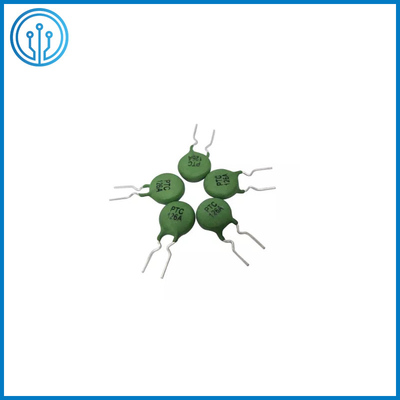
Ceramic PTC Thermistor YS4020 Cross Resettable Fuse 1000V 1100 Ohm 20% Tol For Current Limiting
DESCRIPTION Of The Ceramic PTC Thermistor
PTC THERMISTOR INTENDED FOR USE AS A CURRENT LIMITING PROTECTION DEVICE
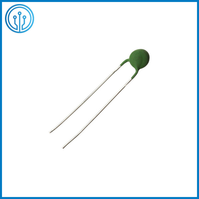
Outline size Of The Ceramic PTC Thermistor
![]()
| Model Number | MZ21-08D112M-102 |
| Dmax(mm) | 9.0 |
| Tmax(mm) | 6.5 |
| W (mm) | 5±1 |
| d(mm) | 0.6±0.05 |
| L1min(mm) | 10 |
| Hmax (mm) | 13.5 |
| Part Number | MZ21-08D112M-102 |
| Product Marking | SCD 102R |
| Coating Material and Color | Green,Silicone Resin |
| Lead | Tin – plated copper wire / Short lead / Side-bend |
Electrical Characteristics (Ta =25℃) Of The Ceramic PTC Thermistor
| Part Number | MZ21-08D112M-102 |
| Rated Resistance Rn (Ω) | 1100±20% |
| Switching Temp. Tc(℃) | 80±10 |
| Withstand voltage Up(V) | ≥1000 |
| Rated Current In(mA) | 10(25±2℃) |
| Switching Current It(mA) | 30(25±2℃) |
| Residual Current Ir(mA) | ≤2 |
| Voltage Surge V(V) | 1000 |
Test item and conditions Of The Ceramic PTC Thermistor
| NO | Test Item | Test Condition | Requirements |
| 1 |
Appearance Overall Dimension Rated zero power resistance |
No visual damage,Pin no oxidation, no broken;Mark shall be complete, clear and identifiable. Measure by vernier caliper. Room Temperature:25±2℃;Place period:≥30min |
Fig.1
Table 1 Table 2 |
| 2 | Switching Temperture | Curie temperature is corresponding value at 2 times of R25 R-T curve. | Table 2 |
| 3 | Withstand voltage | At 25±2℃ ambient environment,voltage 220V,last for 3S ;suddenly changed to 1000V, last 30S then cut off power . |
1000 Visual appearance no visible damage |
| 4 | Non-Operating Current | Place in 25±2℃ still air for 30min, power voltage:220VAC,applying with 30mA current,last 1h ,test its resistance change ratio(Test voltage between two PTC lead with voltmeter ,test PTC current with amperemeter ,then can get resistance of PTC). |
10mA(25±2℃) ┃ Resistance change rate ┃≤50% Inaction for 1 hour |
| 5 |
Action Current
|
After placed in 25±2℃ still air for 30min , power voltage:220VAC,applying with 60Ma current, should go into high-impedance-state in 5 mins. |
30mA Action time ≤5min |
| 6 | Residual current | At 25±2℃ ambient environment,adjust voltage withstand tester to 1000V gradually , steady 10s get reading -current go through PTC,it is residual curent. | ≤2mA |
| 7 | Solderability | Use method of slotted weld ,stain with scaling powder , dip into 230±5℃ lead free tin(Sn96.5Ag3Cu0.5)molten solder groove along the axis direction, last for 3S~5S,body is 5mm far away with molten solder , take out and observe. | The terminals shall be uniformly tinned, and its area≥95% |
| 8 | Resistance to soldering Heat | Use method of slotted weld ,stain with scaling powder , dip into 260±5℃ lead free tin(Sn96.5Ag3Cu0.5)molten solder groove along the axis direction ,last for 3±1S,body is 2mm far away with molten solder,after place in room temperature for 24hours,check appearance and test zero power resistance then compare with initial resistance. |
No visible mechanical damage. ┃Resistance change rate┃≤ 20% |
| 9 | High temperature discontinuous load | According to GB7153 1081th experiment,temp 60±2℃,voltage 265V,initial current 400mA,power on 90min,outage 30min,after total load 1000 hours , place in room temperature for 24hours,check appearance and test zero power resistance then compare with initial resistance. |
No visible mechanical damage. ┃Resistance change rate┃≤ 30% |
| 10 | Strength of lead terminal | Do experiment according to GB2423-29 test U , test Ua, tension 10N and keep 10s ; test Ub , bend 90°,tension 5N,consecutive 2 times ;test Uc , turn around 180° ,consecutive 2 times ; Place in room temperature for 24 hours,test zero power resistance and compare with initial resistance. | ┃Resistance change rate┃≤ 20% |
![]()