


-
 Standard: RoHSNumber: WTH21H06062757C-1Issue Date: 2020-10-22Expiry Date: 2025-10-22
 -
 Standard: REACHNumber: TSNEC2001866403 A01Issue Date: 2020-10-22Expiry Date: 2025-10-22
 -
 Standard: TUVNumber: R50245892Issue Date: 2013-05-02Expiry Date: 2035-05-01
 -
 Standard: CQCNumber: CQC10001052282Issue Date: 2013-12-31Expiry Date: 2035-06-29
 -
 Standard: CQCNumber: CQC07001019009Issue Date: 2013-12-31Expiry Date: 2035-06-29
 -
 Standard: ULNumber: E241319Issue Date: 2019-05-03Expiry Date: 2035-08-02
 -
 Standard: CQCNumber: CQC04001010556Issue Date: 2013-12-31Expiry Date: 2035-09-26
 -
 Standard: CQCNumber: CQC09001033986Issue Date: 2013-12-31Expiry Date: 2035-09-26
 -
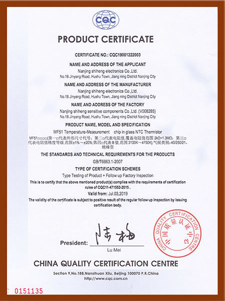 Standard: CQCNumber: CQC19001222003Issue Date: 2013-12-31Expiry Date: 2035-09-26
 -
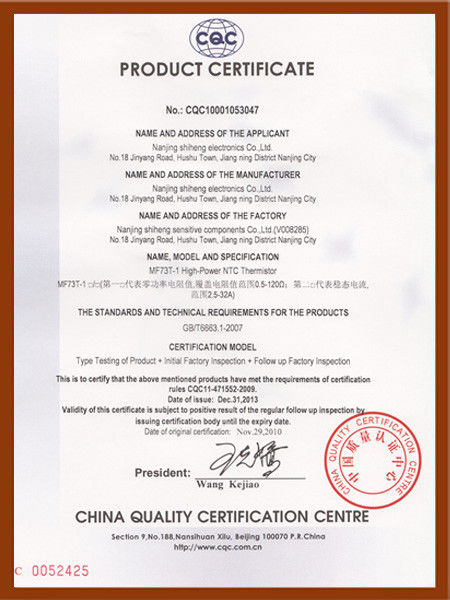 Standard: CQCNumber: CQC10001053047Issue Date: 2013-12-31Expiry Date: 2035-09-26
 -
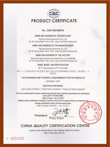 Standard: CQCNumber: CQC13001089724Issue Date: 2013-12-31Expiry Date: 2035-09-26
 -
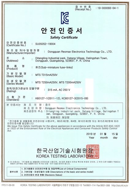 Standard: KC KTLNumber: SU05052-19004Issue Date: 2019-01-15Expiry Date: 2036-01-14
 -
 Standard: VDENumber: 40050560Issue Date: 2019-08-15Expiry Date: 2036-08-14
 -
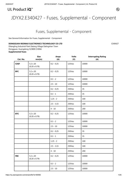 Standard: ULNumber: E340427Issue Date: 2020-05-26Expiry Date: 2038-05-25
 -
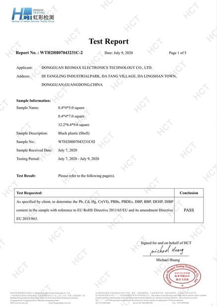 Standard: ROHS 2.0Number: WTH20H07043231C-2Issue Date: 2020-07-09Expiry Date: 2025-07-08
 -
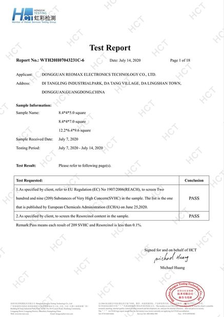 Standard: REACH 210Number: WTH20H07043231C-6Issue Date: 2020-07-14Expiry Date: 2025-07-13
NTC thermistor manufacturing starting materials are different oxides of metals such as manganese, iron, cobalt, nickel, copper and zinc, to which chemically stabilizing oxides may be added to achieve better reproducibility and stability of the NTC thermistor characteristics.
![]()
The oxides are milled to a powdery mass, mixed with a plastic binder and then compressed into the desired shape. The blanks are then sintered at high temperatures (between 1000 °C and 1400 °C) to produce the polycrystalline thermistor body. Disks are contacted by baking a silver paste onto the flat surfaces. Depending on the application, the thermistors are fitted with leads or tab connectors, coated or additionally incorporated in different kinds of housing. Finally the thermistors are subjected to a special aging process to ensure high stability of the electrical values.
The major production process for temperature measurement Leaded NTC thermistor is as following:
![]()
Incoming Inspection
All raw materials, after being received in, are inspected to verify that their physical and electrical attributes are acceptable. A unique ID# is assigned and used for lot traceability.
Raw Material Blend
NTC thermistor manufacturing begins with the precise blending of raw materials into an organic binder solution. These raw materials are powdered transition metal oxides such as manganese, nickel, cobalt, and copper oxides. Other stabilizing agents are added to the mix as well. The oxides and binders are combined using a wet process technique called ball milling. During the ball milling process, the materials are blended and the particle size of the oxide powders are reduced. The completed homogeneous mixture has the consistency of a thick slurry. The exact composition of the various metal oxides and stabilizing agents determines the resistance-temperature characteristics and resistivity of the fired ceramic component.
![]()
Tape Cast
The "slurry" is distributed over a moving plastic carrier sheet using a doctor blade technique. The exact material thickness is controlled by adjusting the height of the doctor blade above the plastic carrier sheet, the carrier sheet speed, and by adjustment of the slurry viscosity. The cast material is dried as it is carried through a long tunnel oven at elevated temperatures on a flat casting belt. The resulting "green" tape is ductile and easily formable. The tape is then subjected to quality inspection and analysis. This thermistor tape is cast in a wide range of thicknesses ranging from as thin as 0.001" to over 0.100" dependent upon the particular component specification.
Wafer Formation
The cast tape now is ready to be formed into wafers. When thin material is needed, the tape is simply cut into small squares. For thicker wafers, the tape is cut into squares which are then stacked one on top of another. These stacked wafers are then laminated together. This allows us to produce wafers to virtually any thickness required. The wafers then go through additional quality testing to ensure high uniformity and quality. Subsequently, the wafers are subjected to a binder burn out cycle. This process removes most of the organic binders from the wafer. Precise time/temperature controls are maintained during the binder burn out cycle in order to prevent unfavorable physical stresses on the thermistor wafers.
Sinter
The wafers are heated to very high temperatures in an oxidizing atmosphere. At these high temperatures, the oxides react with one another and fuse together forming a spinel ceramic matrix. During the sintering process, the material densifies to a predetermined degree and the grain boundaries of the ceramic are allowed to grow. A precise temperature profile is maintained during the sinter process in order to avoid fracturing of the wafers, and to ensure the production of finished ceramic capable of producing components with uniform electrical characteristics. After sintering, the wafers are again subjected to quality inspection and the electrical and physical characteristics are documented.
Electrode
Ohmic contact to the ceramic wafer is obtained using a thick film electrode material. The material is typically silver, palladium-silver, gold, or platinum depending upon the application. The electrode material is comprised of a mixture of metal, glass, and various solvents and is applied to the two opposing surfaces of the wafer or chip by screen printing, spraying, or brushing. The electrode material is fired onto the ceramic in a thick film belt furnace and an electrical union and a mechanical bond forms between the ceramic and the electrode. The metalized wafers are then inspected and the attributes documented. Precise controls during the electrode process ensures that the components produced from the wafers will have exceptional long-term reliability.
![]()
Dice
The electroded thermistor wafers are diced into small chips using high speed semiconductor dicing saws. The saws use diamond blades and are capable of producing high quantities of extremely uniform die. The resulting thermistor chips can be as small as 0.010" square to over 1.000" square. The variance in chip size throughout a group of diced thermistor chips is virtually immeasurable. A typical thermistor wafer can yield thousands of thermistor chips. After dicing, the chips are cleaned and inspected for dimensional and electrical characteristics. The electrical inspection includes verification of nominal resistance value, resistance-temperature characteristics, production yield and the determination of lot acceptability for the particular application. Resistance and resistance-temperature characteristics are measured using precision temperature baths controlled to within as precise as 0.001° Celsius. All test equipment of AMPFORT, is calibrated on a regular basis and is traceable to N.I.S.T. In addition, Littelfuse maintains primary temperature and resistance standards.
Resistance Test
All thermistors are tested for proper resistance value, usually 25°C. The chips are normally tested automatically, but can also be tested manually depending upon the quantity produced and specification. The automatic chip handlers are interfaced with resistance test equipment and computers which are programmed by the operator to place the chips into various bins dependent upon their resistance value. Each automatic chip handler is capable of testing up to 9,000 parts per hour with exceptional accuracy. In addition to the chip sorters, Littelfuse has several automatic leaded component handlers which are capable of sorting the finished thermistors into up to eleven bins. The automatic sorters result in increased product quality as well as reduced lead time and lower costs.
Lead Wire Attachment
In some cases the thermistors are sold in chip form and do not require lead wires, however in most cases, lead wires are required. The thermistor chips are attached to lead wires by either soldering or by pressure contact in a diode style package. In the soldering process, the thermistor chips are loaded on lead frames which rely upon the spring tension of the wires to hold the chip during the soldering process. The assembly is then dipped into a molten solder pot and removed. Dipping speeds and dwell times are precisely controlled in order to avoid subjecting the thermistor to excessive thermal shock. Special fluxing agents are used as well to enhance soldering performance without harming the thermistor chip. The solder adheres to the chip electrode and to the lead wire, thereby, providing a strong bond of the wire to the chip. For the diode style "DO-35" packaged thermistors, the thermistor chip is held between two lead wires in an axial fashion. A glass sleeve is placed around the assembly and the assembly is heated to an elevated temperature where the glass sleeve melts around the thermistor chip and seals to the lead wires. As in diode construction, the pressure that the glass exerts on the assembly provides the necessary contact between the lead wires and the thermistor chip.
The lead wires used on thermistors are typically copper, nickel, or an alloy and are generally tin or solder coated. Low thermally conductive alloy lead wire material may be used in certain applications which require the thermistor to be thermally isolated from the lead wire. In most applications, this allows the thermistor to respond more rapidly to changes in temperature. After attachment, the bond between the lead wire and chip is inspected. A strong solder interface helps guarantee the long-term reliability of the completed thermistor.
Encapsulation
In order to protect the thermistor from the operating atmosphere, humidity, chemical attack, and contact corrosion, the leaded thermistor is often coated with a protective conformal coating. The encapsulant is typically a high thermally conductive epoxy resin. Other encapsulants include silicone, ceramic cement, lacquer, urethane, and shrink sleeving. The encapsulant also assists in assuring good mechanical integrity of the device. Thermal response of the thermistor is taken into consideration when choosing an encapsulating material. In applications where fast thermal response is essential, a thin coat of a high thermally conductive encapsulant is utilized. Where environmental protection is more important, another encapsulant may be chosen. Encapsulants such as epoxy, silicone, ceramic cement, lacquer, and urethane are normally applied using a dip process and the material is either allowed to cure at room temperature or placed in an oven at an elevated temperature. Precise time, temperature, and viscosity controls are used throughout the process in order to ensure that pinholes or other deformities do not develop.
Termination
Thermistors are frequently supplied with terminals attached to the ends of its lead wires. Before the terminals are applied, the insulation on the lead wires is stripped appropriately to accommodate the specified terminal. These terminals are attached to the lead wires using specially tooled application machines. Subsequently, the terminals may be inserted into plastic or metal housings before being shipped to the customer.
Probe Assembly
For environmental protection or for mechanical purposes, thermistors are often potted into probe housings. These housing can be made of materials including epoxy, vinyl, stainless steel, aluminum, brass, and plastic. In addition to providing a suitable mechanical mounting for the thermistor element, the housing protects it from the environment to which it will be subjected. The proper selection of lead wire, lead wire insulation material, and potting material will result in a satisfactory seal between the thermistor and the outside environment.
Marking
The completed thermistor can be marked for easy identification. This can be as simple as a color dot or more complex such as a date code and part number. In certain applications, the coating material on a thermistor body may have dye added in order to obtain a specified color. A color dot is typically added to a thermistor body utilizing a dipping process. Marking that requires alphanumeric characters is produced with a marking machine. This machine simply marks the part with a permanent ink. The ink is cured at an elevated temperature.
Final Inspection
All completed orders are inspected for physical and electrical defects on a "Zero Defect basis". All parameters are inspected and documented prior to shipment of product.
Pack And Ship
All thermistors and assemblies are carefully packaged and tagged with a bar code label containing, as a minimum, the following information:
Part number
Customer's part number
Customer's purchase order number
Date of shipment
Quantity