


|
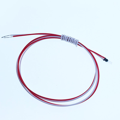
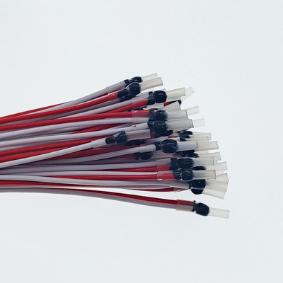
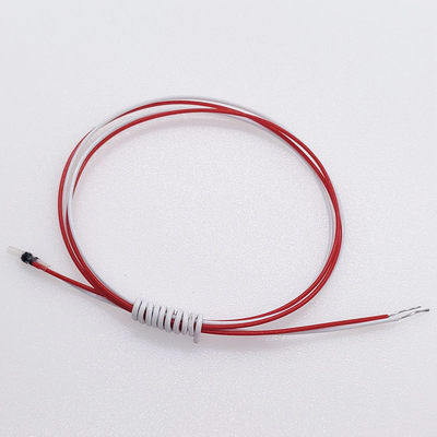
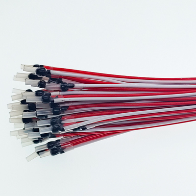
B59100M1180A070 180C Single PTC Thermistor For Motor Winding Protection
Product Details:
| Place of Origin: | Dongguan,China |
| Brand Name: | AMPFORT |
| Certification: | UL |
| Model Number: | MZ6-180-ES |
Payment & Shipping Terms:
| Minimum Order Quantity: | 1000pcs |
|---|---|
| Price: | Negotiable |
| Packaging Details: | Bulk |
| Delivery Time: | 7 workdays |
| Payment Terms: | T/T |
| Supply Ability: | 30000000 Piece/Pieces per Month |
|
Detail Information |
|||
| Name: | Ptc Thermistor For Motor Winding | Rated Action Temperature Tk: | 180℃ |
|---|---|---|---|
| Application: | Thermal Protection | Lead Wire Color: | White-Red |
| Standards: | DN440S1/DIN44S0S | M: | Sensitive Component |
| Z: | Positive Temperature Model | Min Storage Temperature: | -26℃ |
| Max Storage Temperature: | 160℃ | Wire Tension: | Under 10N, 10S Tension Without Damage |
| High Light: | PTC Thermistor For Motor Winding Protection,Single PTC Thermistor,180C PTC Thermistor |
||
Product Description
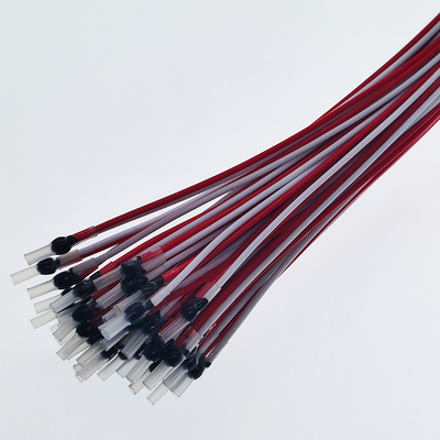
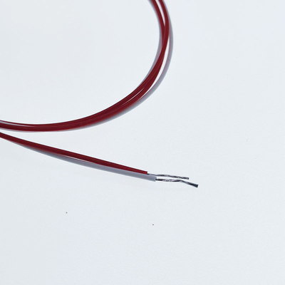
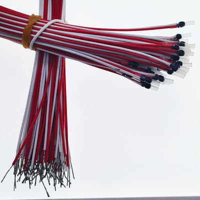
B59100M1180A070 180C Single PTC Thermistor For Motor Winding Protection
![]()
Many electronic products or devices may occur during the operation during operation. During the production process, it is necessary to operate continuously, electrical oven, ball mushroom machines and other mechanical and electrical equipment or high -power power supply, high -power power device heat -calorie products, and other unmanned device. It is more common for accidents caused by overheating or temperature control failure. The use of PTC thermal resistance with overheating protection can effectively prevent accidents.
![]()
![]()
![]()
This product is widely used in the occasion that requires over -temperature protection. The product is installed in a device that requires ultra -temperature protection. The PTC resistance signal is transmitted to the motor protector. When the temperature is close to the temperature and heat -resistant level temperature, the motor protector is disconnected to implement protection.
![]()
1. MZ6 temperature-controlled PTC thermistor series products are divided into two shapes: A-lead type, B-surface paste and installation type
2. Protection temperature range: 60 ~ 130 ℃
3. Fast response time
4. Long -term stability
5. Small size and convenient installation
6. No need to set it up after the product is overheated
![]()
1.MZ6-180-ES Specification
| Name | MZ6 Motor Protection PTC Thermistor |
| Action temperature | 180℃ |
| Color of cable | White-Red |
| Execution standards |
GB/T 7153-2002 Direct thermal step type positive temperature coefficient thermistor Part 1:General specification QUALITY STANDARD: Random testing is carried out according to DGQ P90/P10 (DIN 40080). AQL values can be fixed by arrangement. |
| Dimension and structure | |
| Max DC undamaged voltage | 30V |
| Normal use DC current | Max. 2.5V |
| -20℃~Tk-20℃ | Max. 100 Ohm |
| TK+5℃ | Min. 1330Ohm |
| TK-5℃ | Max. 550Ohm |
| TK+15℃ | Min. 4KOhm |
| Insulation strength (AC) | 2.5KV/60S |
shrink tube housing
![]()
screw in sensors in housing surface mount ring lug
![]()
| Rated operating temperature (℃) | ±Tolerance TROT ±TROT (℃) | Resistance R (Ω)® | Resistance R(Ω)® at PTC thermistor temperature: | Wire Color | |||||||||||||||||||||||||||||||||||
| from -20℃ | TROT –TROT | TROT+TROT | TROT+15k | ||||||||||||||||||||||||||||||||||||
| to TROT -20K | (UKL≤2.5V) | (UKL≤2.5V) | (UKL≤7.5V) | ||||||||||||||||||||||||||||||||||||
| 30 | ±5 | ≤100 | Brown/Black | ||||||||||||||||||||||||||||||||||||
| 40 | Brown/Red | ||||||||||||||||||||||||||||||||||||||
| 50 | Brown/Gray | ||||||||||||||||||||||||||||||||||||||
| 60 | ≤570 | ≥570 | - | White/Gray | |||||||||||||||||||||||||||||||||||
| 70 | ≤570 | ≥570 | - | White/Brown | |||||||||||||||||||||||||||||||||||
| 80 | ≤570 | ≥570 | - | White/White | |||||||||||||||||||||||||||||||||||
| 90 | ≤550 | ≥1330 | ≥4000 | Green/Green | |||||||||||||||||||||||||||||||||||
| 100 | ≤550 | ≥1330 | ≥4000 | Red/Red | |||||||||||||||||||||||||||||||||||
| 105 | ≤550 | ≥1330 | ≥4000 | Blue/Gray | |||||||||||||||||||||||||||||||||||
| 110 | ≤550 | ≥1330 | ≥4000 | Brown/Brown | |||||||||||||||||||||||||||||||||||
| 115 | ≤550 | ≥1330 | ≥4000 | Blue/Green | |||||||||||||||||||||||||||||||||||
| 120 | ≤550 | ≥1330 | ≥4000 | Gray/Gray | |||||||||||||||||||||||||||||||||||
| 125 | ≤550 | ≥1330 | ≥4000 | Red/Green | |||||||||||||||||||||||||||||||||||
| 130 | ≤550 | ≥1330 | ≥4000 | Blue/Blue | |||||||||||||||||||||||||||||||||||
| 135 | ≤550 | ≥1330 | ≥4000 | Red/Black | |||||||||||||||||||||||||||||||||||
| 140 | ≤550 | ≥1330 | ≥4000 | White/Blue | |||||||||||||||||||||||||||||||||||
| 145 | ≤550 | ≥1330 | ≥4000 | White/Black | |||||||||||||||||||||||||||||||||||
| 150 | ≤550 | ≥1330 | ≥4000 | Black/Black | |||||||||||||||||||||||||||||||||||
| 155 | ≤550 | ≥1330 | ≥4000 | Blue/Black | |||||||||||||||||||||||||||||||||||
| 160 | ≤550 | ≥1330 | ≥4000 | Blue/Red | |||||||||||||||||||||||||||||||||||
| 165 | Blue/Brown | ||||||||||||||||||||||||||||||||||||||
| 170 | ±7 | ≤570 | ≥570 | - | White/Green | ||||||||||||||||||||||||||||||||||
| 180 | ≤570 | ≥570 | - | White/Red | |||||||||||||||||||||||||||||||||||
2.Color Vs Temperature Of PTC Thermistor Sensor
The color of the connection leads indenfies the rated response temperature. These are defined in DIN 44081/082.
|
Action Temperature Tk |
Color of wire | |
| 60°C | White | Gray |
| 70°C | White | Brown |
| 80°C | White | White |
| 90°C | Green | Green |
| 100°C | Red | Red |
| 105°C | Blue | Gray |
| 110°C | Brown | Brown |
| 115°C | Blue | Green |
| 120°C | Gray | Gray |
| 125°C | Red | Green |
| 130°C | Blue | Blue |
| 135°C | Red | Black |
| 140°C | White | Blue |
| 145°C | White | Black |
| 150°C | Black | Black |
| 155°C | Blue | Black |
| 160°C | Blue | Red |
| 165°C | Blue | Brown |
| 170°C | White | Green |
| 180°C | White | Red |
3.Technical Specifications
| Technical Specifications | Single PTC | Triple PTC | Units | |
| Max working voltage | Umax | 30 | 30 | V |
| Normal using voltage | V | Max 2.5 | Max 2.5 | V |
| Rated action temperature | Tk | 60~180 | 60~180 | ℃ |
| Tk tolerance | ±5 | ±5 | ℃ | |
| Tk repeatability | T | ±0.5 | ±0.5 | ℃ |
|
Resistance in norm al temperature T=25±1℃(V Max2.5V) |
R25 | Max 100 | Max 300 | Ohm |
|
PTC resistance at some temperature(V Max2.5V) |
TK-5℃ | Max550 | Max 1650 | Ohm |
|
PTC resistance at some temperature(V Max2.5V) |
Tk+5℃ | min. 1330 | min. 3990 | Ohm |
|
PTC resistance at some temperature(V Max2.5V) |
Tk+15℃ | min. 4 | min. 12 | KOhm |
| -20℃~Tk-20℃ | Max 250 | Max750 | Ohm | |
| Tk reaction time | Td | less than 5 | less than 5 | S |
| Insulation strength | V | 2.5 | 2.5 | KV |
| Maximum storage temperature | T1max | 125 | 125 | ℃ |
| Minimum storage temperature | T1min | -25 | -25 | ℃ |
| Lead wire color | See the colorful coding below | |||
| Weight | Wt | 2 | 3.5 | g |
4.PTC Characteristic Curve
![]() 5.Operating Instruction
5.Operating Instruction
The electric motor of different insulation rank selects the different Tk temperature thermistor, its parameter is shown at following table(only reference).
| Electric motor insulation rank | Limited Working Temperature | Thermistor(TK) |
| Y | 90 | 80~85℃ |
| A | 105 | 95~100℃ |
| E | 120 | 110~115℃ |
| B | 130 | 120~125℃ |
| F | 155 | 145~150℃ |
| H | 180 | 170~175℃ |
| C | Above 180 | Above 180 |
6.Note for mounting
![]()
1.Insert wire in the winding wire slot of the motor,make it tidy, and then mount the PTC thermistor in the coil of motor(as shown in figure).
2.White mounting,do not hard beat or press the sensing area of the thermistor for fear that the internal precise structure of the product might be damaged.
3. While mounting,do not extremely hard pull the outgoing line of the product for fear that the outgoing line might be pulled apart.
4.Before connecting,read the technical information about PTC temperature control module(the former GRB motor overheat protector) for fear that the thermistor might be damaged.
5.Securely connect the outgoing line in the specified connection position.
7.Error and Measure
| Breakdown | Reason | Measure |
| Resistance value is too high(measure resistance of the outgoing line by Ohm band of an AVO meter,the resistance value of a single line is higher than 100 Ohm at 25℃) |
1. The lead of the thermistor opened a way or was in a bad contact. 2. The thermistor was damaged. |
1.Check the lead of the thermistor whether open or not,or in the bad contact 2.Replace the themistor |
| Resistance value is too high(measure resistance of the outgoing line by Ohm band of an AVO meter,the resistance value of a single line is higher than 20 Ohm at 25℃) |
1.The lead of thermistor was in short circuit; 2.The thermistor was damaged
|
Check the lead of the thermistor is in short circuit or not,and connect it. 2,Replace the thermistor
|
| Sometimes be Normal,Sometimes be abormal, |
1.The lead of thermistor was in in bad contact; 2.The thermistor was damaged
|
Connect the lead of the thermistor and the binding post tightly. 2.Replace the thermistor |
8. UR Listing
| PTC sensor | ||||
| Thermistor-type Devices - Component XGPU2 | ||||
| Model No. | Resistance at 25°C (k ohm) | Tmoa (°C) | Class | CA |
| MZ6-100 | 0.03-0.1 | 115 | C3 | 4# |
| MZ6-105 | 0.03-0.1 | 120 | C4 | 4# |
| MZ6-110 | 0.03-0.1 | 125 | C4 | 4# |
| MZ6-115 | 0.03-0.1 | 130 | C4 | 4# |
| MZ6-120 | 0.03-0.1 | 135 | C4 | 4# |
| MZ6-125 | 0.03-0.1 | 139 | C4 | 4# |
| MZ6-130 | 0.03-0.1 | 139 | C4 | 4# |
| MZ6-135 | 0.03-0.1 | 135 | C4 | 4# |
| MZ6-140 | 0.03-0.1 | 140 | C4 | 4# |
| MZ6-145 | 0.03-0.1 | 145 | C4 | 4# |
| MZ6-150 | 0.03-0.1 | 150 | C4 | 4# |
| MZ6-155 | 0.03-0.1 | 155 | C4 | 4# |
| # Indicates unique Condition of Acceptability | ||||
9. OPERATION
PTC thermistors exhibit very high sensitivity over a narrow temperature band. For temperature measuremen in this range, NTC thermistors are easier to measure and more accurate. PTC thermistors are especially suited as temperature sensors for monitoring the windings of electric machines, and also for use in simple fail-safe circuitry. When a given temperature (nominal response temperature qNAT) is exceeded, the circuit can be switched off through a relay or amplifier, since the PTC-sensor will have an extremely high ohmic value in the region of its response temperature. This will have the same effect as a break in the circuit or a failure of the thermistor.
10.INSTALLATION TIPS
For PTC temperature sensors in electrical windings:
- the thermistors can only be inserted in the windings before impregnation - it is advisable to embed one in each phase, if possible in the centre of the coil generating most heat, and generally on the outflow side of any air movement
- air inflow onto the temperature sensor will interfere with heat transfer
- if using varnish/lacquer which is not chemically neutral, suitability tests must be undertaken by the customer
- WARNING! It is very important that the sensor must be installed parallel with the copper of the winding, so that the teflon leads can assume the form of the rest of the winding and thereby retain the high- voltage resistance rating.
11.Cross References List
| AMPFORT P/N | EPCOS P/N |
| MZ6-60-ES | B59100M1060A070 |
| MZ6-70-ES | B59100M1070A070 |
| MZ6-80-ES | B59100M1080A070 |
| MZ6-90-ES | B59100M1090A070 |
| MZ6-100-ES | B59100M1100A070 |
| MZ6-110-ES | B59100M1110A070 |
| MZ6-120-ES | B59100M1120A070 |
| MZ6-130-ES | B59100M1130A070 |
| MZ6-140-ES | B59100M1145A070 |
| MZ6-145-ES | B59100M1140A070 |
| MZ6-150-ES | B59100M1150A070 |
| MZ6-155-ES | B59100M1155A070 |
| MZ6-160-ES | B59100M1160A070 |
| MZ6-170-ES | B59100M1170A070 |
| MZ6-180-ES | B59100M1180A070 |
| MZ6-060-DS | B59300M1060A070 |
| MZ6-070-DS | B59300M1070A070 |
| MZ6-080-DS | B59300M1080A070 |
| MZ6-090-DS | B59300M1090A070 |
| MZ6-100-DS | B59300M1100A070 |
| MZ6-110-DS | B59300M1110A070 |
| MZ6-120-DS | B59300M1120A070 |
| MZ6-130-DS | B59300M1130A070 |
| MZ6-140-DS | B59300M1140A070 |
| MZ6-145-DS | B59300M1145A070 |
| MZ6-150-DS | B59300M1150A070 |
| MZ6-155-DS | B59300M1155A070 |
| MZ6-160-DS | B59300M1160A070 |
| MZ6-170-DS | B59300M1170A070 |
| MZ6-180-DS | B59300M1180A070 |
![]()
![]()
![]()
![]()
![]()
![]()
![]()
![]()
![]()
![]()
![]()
![]()
![]()
![]()
![]()
![]()
![]()
![]()
![]()