


|
CPTC Ceramic PTC Thermistor 1500 Ohm Ih 14mA It 28mA 80C 265V Resettable Fuse For Overcurrent Overvoltage Protection
Product Details:
| Place of Origin: | Dongguan,China |
| Brand Name: | CNAMPFORT |
| Certification: | ROHS |
| Model Number: | MZB-06H152RM265 |
Payment & Shipping Terms:
| Minimum Order Quantity: | 5000 |
|---|---|
| Price: | Neogitable |
| Packaging Details: | Bulk |
| Delivery Time: | 2 Weeks |
| Payment Terms: | T/T |
| Supply Ability: | 2KKPCS PER MONTH |
|
Detail Information |
|||
| Name: | CPTC Ceramic PTC Thermistor | Marking: | 152 |
|---|---|---|---|
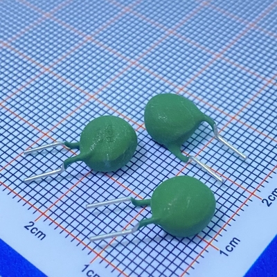
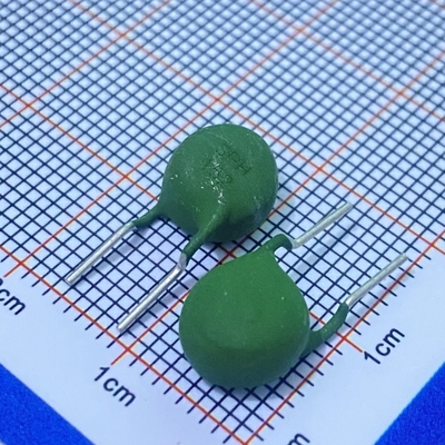
| Dmax: | 6.5mm | Tmax: | 5.5mm |
| Pitch F: | 5.0±0.5mm | Wire Diameter: | 0.60±0.05mm |
| Coating: | Silicone Resin | Color: | Green |
| Lead Wire: | Tinned Copper Wire,Inside Kink | R25: | 1500 Ω±20% |
| Ih: | 14mA | It: | 28mA |
| Curie Temperature: | 80±10℃ | Residual Current: | <4mA |
| High Light: | Ceramic PTC Thermistor,PTC Thermistor 265V |
||
Product Description
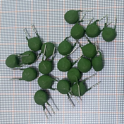
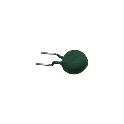
CPTC Ceramic PTC Thermistor 1500 Ohm Ih 14mA It 28mA 80C 265V Resettable Fuse For Overcurrent Overvoltage Protection
![]()
MZB/MZ11 series PTC thermistor is a "10,000 times fuse" with automatic protection, automatic recovery, no contact, no noise, no spark, or "self-recovery fuse", which is the successor to "thermal fuse" and " The third-generation protection device launched after the "temperature switch".
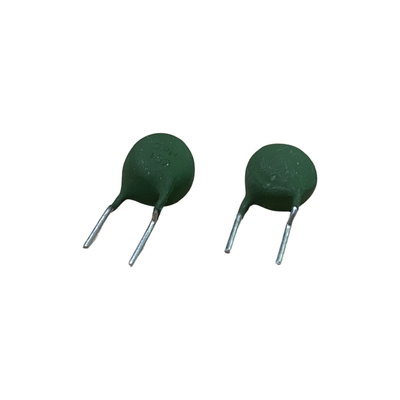
These directly heated ceramic-based thermistors have a positive temperature coefficient and are primarily intended for overload protection. They consist of a ceramic pellet soldered between two tinned CCS wires and coated with a 94 V-0 high temperature hard silicone lacquer.
PTC thermistor for overcurrent protection is a protective element that automatically protects and automatically restores abnormal temperatures and abnormal currents. It is commonly known as "resettable fuse" and "10,000 fuses". It replaces traditional fuses, which can be widely used for overcurrent protection of motors, transformers, switching power supply, electronic lines, etc. The protection element of the type of anomaly and abnormal currents and automatic recovery is limited to the residual current value in the entire line. The traditional fuse cannot be recovered after the line is melted, and the PTC thermistor can be restored to the pre -protection state after the failure is removed. When the failure occurs again, it can achieve its overheating protection function.
![]()
![]()
Computers and peripherals, communications and network equipment, motors, transformers portable electronic products, consumer electronics, automotive, industrial electronics and other products over-current overheating protection
Smart watt-hour meters, multimeters, chargers, small transformers, digital multimeters, micro motors, small electronic instruments, etc.
Overload (current, voltage, temperature) protection in:
• Industrial electronics
• Consumer electronics
• Electronic data processing
• Overcurrent protection
• Short circuit protection
![]()
Complete range of models, products of various sizes and currents, with a wide range of applications to meet the needs of different products; stable performance, good reliability, and good consistency.
Small size, low power consumption, short response time, self-recovery, no noise, long and reliable, in line with ROSH standards, various electrical parameters of the over-current protection overheating thermistor can be customized based on customer requirement
1. MZB series PTC thermsitor is pins wire coated parts.
2. Can operate in high current
3. Suitable to operate continuously in 30/60VAC(high resistance state)
4. has complete parts
5. Long stability.
6. Do not need to be reset after protection.
7. No contact point, no noise.
• Wide range of trip and non-trip currents: From 11 mA up to 800 mA
• Small ratio between trip and non-trip currents (It/Int = 1.5 at 25 °C)
• High maximum inrush current (up to 5.5 A)
• Leaded parts withstand mechanical stresses and vibration
• Meet XGPU standard UL1434
![]()
1.Dimension & Electrical Performance
![]()
3. Series Specification
Technical parameter(general circuit overcurrent protection)
| Type | R25(Ω) | Imax(A) | In(mA) | It(mA) | Vmax(V) | Size(mm;max) | |||
| D | T | W | d | ||||||
| MZ2J-181MU030 | 180±20% | 0.3 | 30 | 75 | 125 | 6 | 5 | 5 | 0.6 |
| MZ2J-150PU028 | 150±25% | 0.2 | 28 | 78 | 265 | 6 | 6 | 5 | 0.6 |
| MZ2J-180MU029 | 180±20% | 0.3 | 29 | 70 | 265 | 6.5 | 6.5 | 5 | 0.6 |
| MZ2J-470NU030 | 47±30% | 1.5 | 30 | 140 | 32 | 7.4 | 4 | 5 | 0.6 |
| MZ2J-330MU100 | 33±20% | 0.5 | 100 | 230 | 140 | 7.4 | 6 | 5 | 0.6 |
| MZ2J-820MU060 | 82±20% | 0.5 | 60 | 150 | 265 | 8.2 | 6.5 | 5 | 0.6 |
| MZ2J-620PU680 | 62±25% | 1 | 68 | 190 | 265 | 8 | 6 | 5 | 0.6 |
| MZ2J-3R3NU140 | 3.3±30% | 2 | 140 | 580 | 24 | 99.5 | 4 | 5 | 0.6 |
| MZ2J-3R9MU210 | 3.9±20% | 2 | 210 | 550 | 56 | 10.5 | 4 | 5 | 0.6 |
| MZ2J-390MU100 | 39±20% | 1.2 | 100 | 240 | 265 | 10 | 6.5 | 5 | 0.6 |
| MZ2J-220MU135 | 22±20% | 0.8 | 135 | 340 | 125 | 10 | 5.5 | 5 | 0.6 |
| MZ2J-100MU220 | 10±20% | 1 | 220 | 510 | 140 | 13 | 6 | 7.5 | 0.8 |
| MZ2J-0R8PU680 | 0.8±25% | 5.5 | 680 | 1900 | 30 | 13.5 | 4 | 7.5 | 0.8 |
| MZ2J-100MU220 | 10±20% | 1.2 | 220 | 550 | 125 | 15 | 5.5 | 7.5 | 0.8 |
| MZ2J180MU180 | 18±20% | 1.8 | 180 | 440 | 265 | 15.7 | 6.5 | 7.5 | 0.8 |
| MZ2J-5R6MU340 | 5.6±20% | 2 | 340 | 780 | 140 | 17 | 6 | 7.5 | 0.8 |
| MZ2J-6R8MU300 | 6.8±20% | 1.4 | 300 | 750 | 125 | 18.5 | 5.5 | 7.5 | 0.8 |
| MZ2J-4R7MU360 | 4.7±20% | 1.7 | 360 | 900 | 125 | 18.5 | 5.5 | 7.5 | 0.8 |
| MZ2J-3R3MU420 | 3.3±20% | 2 | 420 | 1050 | 125 | 18.5 | 5.5 | 7.5 | 0.8 |
| MZ2J-6R0PU300 | 6±25% | 4.1 | 300 | 830 | 265 | 18.5 | 6 | 7.5 | 0.8 |
![]()
![]()
![]() 3.1 Select PTC thermistor as an overcurrent heat protection element for overcurrent protection. First of all, confirm that the maximum normal working current (that is, the non -action current of PTC thermistor for overcurrent protection) and the installation position of PTC thermal resistance (PTC thermal resistance ( At the time of normal work), the highest ambient temperature, followed by the protection current (that is, the action current of PTC thermistor with PTC), the maximum working voltage, the rated zero power resistance, and the shape size of the component. As shown in the figure below: the relationship between the environmental temperature, the non -action current and the action current.
3.1 Select PTC thermistor as an overcurrent heat protection element for overcurrent protection. First of all, confirm that the maximum normal working current (that is, the non -action current of PTC thermistor for overcurrent protection) and the installation position of PTC thermal resistance (PTC thermal resistance ( At the time of normal work), the highest ambient temperature, followed by the protection current (that is, the action current of PTC thermistor with PTC), the maximum working voltage, the rated zero power resistance, and the shape size of the component. As shown in the figure below: the relationship between the environmental temperature, the non -action current and the action current.
![]()
3.2 Application principle
When the circuit is in a normal state, the current of the PTC thermistor with PTC is less than the rated current by overcurrent protection. PTC thermistor is in normal state, and the resistance value is small, which will not affect the normal operation of the protected circuit. When the circuit fails and the current exceeds the rated current, the heating resistance of PTC for overcurrent protection is suddenly heated, which is high-resistant, which makes the circuit in a relatively "disconnect" state, thereby protecting the circuit from damaging. When the failure is eliminated, the PTC thermistor is also automatically responded to the low -resistance state, and the circuit is restored to normal work.
![]()
The picture above is a diagram of the Fu-Ante curve and load curve of the circuit when working normally. From point A to point B, the voltage applied to PTC thermist resistance gradually increases, and the current flowing through the PTC thermistor is also linear. It indicates that the resistance value of the PTC thermistor is basically unchanged, that is, keep at a low -resistant state; from point B to point E, the voltage gradually increases, and the PTC thermistor is increased rapidly due to the heating resistance. The rapid decrease in the current indicates that the PTC thermistor enters the protection state. The normal load curve is lower than point B, and the PTC thermal resistance will not enter the protection state.
Generally speaking, there are three types of overcurrent and heat protection:
1. current overcurrent (Figure 3): RL1 is the load curve during normal working. When the load resistance value is reduced, such as the transformer line is short -circuited, the load curve changes from RL1 to RL2, exceeding B,ptc thermistor go into protection state;
![]() 2.Voltage overcurrent (Figure 4): The power supply voltage increases. For example, the 220V power cable suddenly rises to 380V, and the load curve changes from RL1 to RL2, exceeding point B, and PTC thermistor to enter the protection state;
2.Voltage overcurrent (Figure 4): The power supply voltage increases. For example, the 220V power cable suddenly rises to 380V, and the load curve changes from RL1 to RL2, exceeding point B, and PTC thermistor to enter the protection state;
![]()
3,Temperature overheating (Figure 5): When the ambient temperature rises exceeds a certain limit, the PTC thermistor V-I curve has changed from A-B-E to A-B1-F, the load curve RL exceeds B1 points, and PTC thermistor to enter the protection state;
![]()
Overcurrent protection circuit diagram
![]()
Ordering Info
![]()
PTC thermistor resistance for general line transfers protection
![]()
![]()
3,The maximum current allowed when the maximum working voltage
When the PTC thermistor is required to perform the protection function, check whether there is a condition in which the maximum current that generates the maximum current in the circuit. Generally, it means that the user has a short -circuit possibility. The specification book has given the maximum current value. When the value exceeds this value, it can cause PTC thermistor damage or early failure.
4,Switch temperature (Curie temperature)
We can provide overcurrent protection components of Curie temperature 80 ° C, 100 ° C, 120 ° C, and 140 ° C. On the one hand, the non -action current depends on the diameter of Curie temperature and PTC thermal electricity chip. Select the temperature and small -sized components of high -ranking high -ranking mortis; on the other hand, you must consider that the PTC popular resistor will have higher surface temperatures, whether it will cause unwilling side effects on the line. Under normal circumstances, the environmental temperature of Curie is 20 ~ 40 ℃ exceeding the highest use of the highest use of the highest use of the highest use of the ambient temperature.
5,The impact of the environmental environment
When contacting chemical reagents or using irrigation or fillers, it is necessary to be specially careful to be reduced to the reduction of the PTC thermistor resistance effect, and the change in heat conditions caused by irrigation may cause the PTC thermistor resistor to partial parts Damage is overheated.
Attachment: Power transformer overcurrent protection PTC thermistor selection example
It is known that the primary voltage of a power transformer is 220V, the secondary voltage is 16V, the secondary current is 1.5A, and the primary current when the secondary is abnormal is about 350mA. The temperature rises at 15-20 ° C, and the PTC thermistor is close to the transformer installation. Please select a PTC thermistor to be used for primary protection.
1. Determine the maximum working voltage
The working voltage of the transformer is 220V. Considering the factors of power fluctuations, the maximum working voltage should reach 220V × (1+20%) = 264V
The maximum working voltage of PTC thermistor is 265V.
2. Determine the non -action current
After calculation and actual measurement, the primary current is 125mA when the transformer work normally. Considering that the environmental temperature of the installation location of the PTC thermistor is up to 60 ° C, it is determined that the non -action current should be 130 ~ 140mA when 60 ° C.
3. Determine the action current
Considering that the ambient temperature of the installation position of the PTC thermistor can reach -10 ° C or 25 ° C, it can be determined that the action current should be 340-350mA when the action current is -10 ° C or 25 ° C, and the action time is about 5 minutes.
4. Determine the rated zero power resistance R25
The PTC thermistor is connected in the junior. The voltage of the generated voltage should be as small as possible. 200V × 1%÷ 0.125A = 17.6Ω
5. Determine the maximum current
After actual measurement, the primary current can reach 500mA when the transformer is short -circuit. If considering that the primary coil has a part of the short circuit, a larger current passes, the maximum current of the PTC thermistor is determined to be above 1A.
6. Determine the temperature and appearance size
Considering that the environmental temperature of the installation location of the PTC thermistor can reach up to 60 ° C, when choosing Curie temperature, it increases by 40 ° C, and the centered temperature is 100 ° C. The device is not installed in the transformer line package. The higher surface temperature does not have a bad effect on the transformer. The temperature of the residence can be selected at 120 ° C. In this way, the diameter of the PTC thermistor can be reduced by one gear and the cost can be reduced.
7. Determine the PTC thermist resistor model
According to the above requirements, check the specifications of our company, select MZ11-10P15RH265, that is: maximum operating voltage 265V, rated zero power resistance value 15Ω ± 25%, non-action current 140 mA, action current 350 mA, maximum current 1.2A, home The temperature is 120 ° C, and the maximum size is 11.0mm.
PTC's failure mode
There are two main indicators to measure the reliability of PTC thermistor:
A. The ability to resist voltage-exceeding the specified voltage can cause short-circuit breakdown of the PTC thermistor resistor. Applying high voltage products to eliminate low-voltage resistance products to ensure that the PTC thermistor is below the maximum working voltage (VMAX). safe;
B. The ability to resist current-exceeding the specified current or switching times can cause PTC thermistor resistors to present an irreplaceable high-resistant state and failure. The circulating interrupt test cannot eliminate the early failure of the early failure.
Under the prescribed use conditions, the PTC is high -resistant after the PTC fails. Long -term (generally greater than 1000 hours) The voltage applied to the PTC thermistor is very small, which causes a very small range of normal temperature resistance. The PTC heating element with a lily of more than 200 ° C is relatively obvious. In addition to the PTC heating element, the main reason for the failure of the PTC is due to stress cracking in the ceramic body center in the switch operation. During the movement of the PTC thermal simulation resistor, the uneven distribution of temperature, resistivity, electric field, and power density in the PTC porcelain sheet caused a large stress and layered cracking.
Precautions
1. Welding
When welding, it should be noted that the PTC thermistor cannot be damaged due to excessive heating. The highest temperature, the longest time and the shortest distance must be observed below:
Welding soldering iron welding
The temperature of the molten pond MAX*.260 ℃ max*.360 ℃
*Welding time Max*.10s max*.5s
The smallest distance from the PTC thermistor is min.6mm min.6mm
Under worst welding conditions, it will cause changes in resistance.
2. Coating and irrigation
When coating and irrigation are added to the PTC thermistor, mechanical stress is not allowed to appear due to different thermal expansion in solidification and subsequent treatment. Please use irrigation materials or fillers carefully. The upper limit temperature of the PTC thermistor is not allowed during curing. In addition, it should be noted that irrigation materials must be chemical neutral. The restoration of titanate ceramics in PTC thermistor may cause reduced resistance and loss of electrical performance; changes in thermal heat dissipation conditions due to irrigation may cause local overheating on PTC thermistor, which causes it destruction.
3. Clean
Freon, methane or vitaminyl chloride and other mild cleaning agents are suitable for cleaning. It can also use ultrasonic waves, but some cleaning agents may damage the performance of thermistor. It is best to test it before cleaning or consult our company.
4. Storage conditions and duration
If the storage period is properly stored, there is no time limit for the storage period of the PTC thermistor. In order to maintain the weldability of the PTC thermistor, it should be stored in an atmosphere without erosive. At the same time, pay attention to air humidity, temperature and container materials. The original should be stored in the original packaging as much as possible. The touch of the metal coverage layer of the unwalked PTC thermistor may cause a reduced weldable performance. At the exposure of overcorders or over -high temperatures, the performance of some specifications of products may change, such as weldability of tin lead, but it can be stored for a long time under normal electrical component preservation conditions.
5. Precautions
In order to avoid accidents/short circuit/burning such as PTC thermistor, when using (test) PTC thermistor, you should pay special attention to the following matters: Do not use it in oil or in water or flammable gas, (test) PTC thermistor; do not use (test) PTC thermistor resistor under the condition that exceeds the "maximum working current" or "maximum working voltage" conditions.
6.MOUNTING
PTC thermistors can be mounted by wave, reflow, or hand-soldering. Current levels have been determined according IEC 60738 conditions. Different ways of mounting or connecting the thermistors can influence their thermal and electrical behavior. Standard operation is in still air, any potting or encapsulation of PTC thermistors is not recommended and will change its operating characteristics.
Typical Soldering
235 °C; duration: 5 s (Lead (Pb)-bearing)
245 °C, duration: 5 s (Lead (Pb)-free)
Resistance to Soldering Heat
260 °C, duration: 10 s max.
![]()
![]()
![]()
![]()
![]()
![]()
![]()
![]()
![]()
![]()
![]()
![]()